Ten
3K Member

Posts: 3,432
Likes: 1,467
70 Shasta 16SC + 1964 Airflyte
Currently Offline
|
Post by Ten on Dec 24, 2014 18:47:37 GMT -8
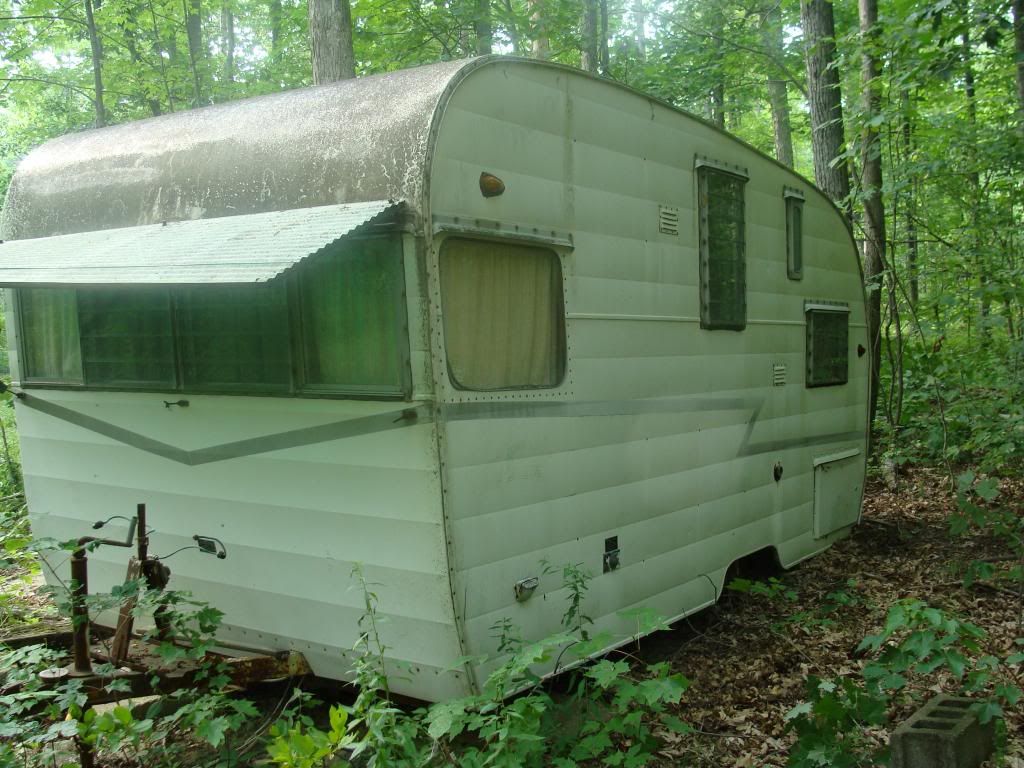
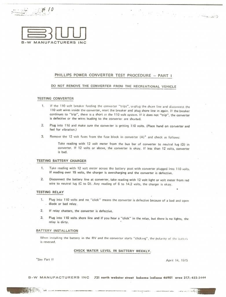
Philips converter and charger. Here is what I know..."PC" means "Philips Converter", 201 = designation for 20 amps; A-1 is the unit with the battery-charging unit, (A-2 is the unit without the charger). I am considering adding this to the SC. But I have a few questions that I am sure someone has already answered, but I cannot find the answers, so here goes. 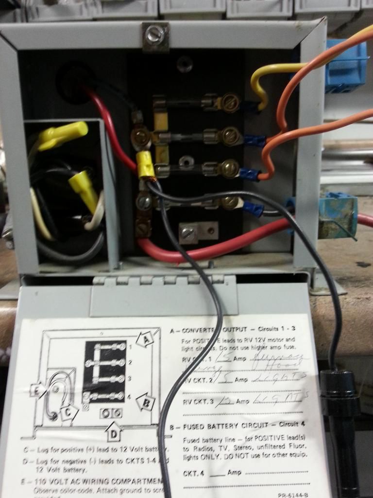 I bought this unit used, out of an older Shasta, well-loved and used decades ago.... so I was pleasantly surprised when I wired it up and plugged it in, and it didn't shoot flames out the vents. It whirred to life and lit my test light on all the outlet wires. It has three outputs, which were labeled as shown above. There are two different circuits coming from the innerds to the fuse panel. I decided to put my meter on it, and found a full 13 volts output at the top 3 outputs. The bottom one (which is also the fused charging circuit) read 9 to about 10.2 volts. So the first question is: Is that normal being that the unit is not tied into any load, or battery storage against it? Or is there maybe an adjustment that can be made? The reason I think any of that is possible is because it is labeled as a circuit for electronics that require "clean" 12 volt power...which I have never heard of. If the charging circuit does not work, there is no sense to pursuing this any further. I know that a brand new unit makes a lot more sense, but when I told Mama about how much the marker lights, tires, brakes, cushions, etc. etc. etc were adding up to, I believe there may be parts of my body that are in jeopardy already.  The 12-volt system in the Shasta is divided into two distinct sections. There is a heavy lead in from the battery box. When hooked up, this lead runs the water pump. There is also a lighter (probably 12-gauge wire) lead that came from the vehicle plug. This side runs in and powers the three overhead 12-V lights. So far I have not found a crossover, that would allow the lights to run from the battery. There is also not a crossover the other way, that would allow the battery to be recharged from the vehicle when plugged in. Adding the charger/converter makes sense to me. I have a feeling that there is something I am overlooking. The good news there is that all of it seems to work except the 12-v light in the bathroom. Rewiring it would not be a huge undertaking, so I'm not scared. |
|
|
|
Post by vikx on Dec 24, 2014 22:43:48 GMT -8
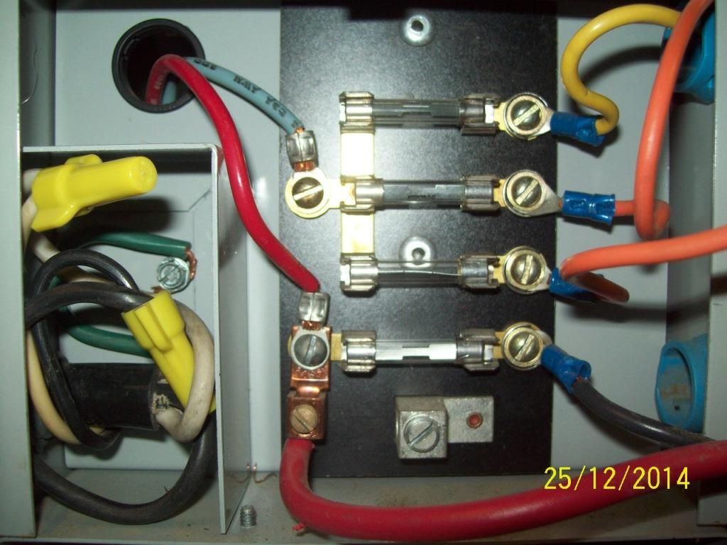
Let's start with the box: Perfect for use as a fuse block and hopefully charger.
1.First of all, a battery is needed for a "buffer". It regulates the 12 volts going out and helps keep weird things from happening. It's not critical, but makes 12 volt life easier. I believe circuit #4 has to be buffered to provide a clean 12 volts. (some electronics require a steady 12+ volts without wild fluctuations, including RV Fridges, which the battery regulates)
2.Also, the ground isn't connected. Even tho there is a 110 ground to frame (guessing), there still should be a Ground for the 12 volt system.
3. The hot side of the fuse block appears to connect to circuit #4? Hard to see. If not, then the output should be at least 12.6 but I'm thinking 13 since 1-3 are at 13. A battery may be necessary and/or that circuit is not working properly. Easy test is to connect battery. Also, it's not uncommon for the charging circuit to fail in older chargers. Does this unit have a circuit board? Might see if there's any burned areas...
Solution: use a separate Maintainer to charge the battery on shore power. Not quite as handy as an all in one unit, but cheaper than going all new. I've been using them for several years with very good luck.
Trailer system:
1. The heavy incoming wire should feed the fuse block from the Battery Hot. Other 12 volt circuits can be powered from there. The pump and a cigar plug can be on 1, lights on 2, and 3 for extras. (porch, another cigar, etc)
2. The 12ga circuit wiring powered from the Vehicle can be switched to fuse block circuit #2. Disconnect the vehicle wire. I'm guessing (with a 7 way plug) that it may be the charge wire, so would go to Battery Hot. I use a self resetting circuit breaker for the Hot wire, but a fuse will work fine.
NOTE: Some older trailers used the TailMarker wire to power inside 12 volt lighting. When the automobile park lights were on, the trailer lights worked. A simple fix to disconnect the TM wire and power the lighting via the fuse block.
3. Test the wiring in the bathroom, it may be that the fixture is dirty, switch bad, that kind of thing.
On to 7 way: I always use a junction box under the tongue area to connect. Easy testing and repairs then.
1. According to the 7 way diagram, Black is Hot and the charge line from the vehicle. The Battery Hot, Charge line and Trailer Hot IN connect together in the J box. (if you have a break away, one wire connects to Hot the other to Brakes Hot, Blue)
2. Of course RT, LT and TM (tails/markers) are connected to the tow wiring.
3. Ground is Ground is Ground, hopefully all white and cleanly connected, yada yada
Last Point, I'm hoping the 110 side of the converter is connected to a breaker box? Trailer should have at least two circuits?
I think you have done well and didn't miss much. It's just a matter of tinkering with it... Looking forward to questions.
|
|
|
|
Ten
3K Member
Posts: 3,432
Likes: 1,467
70 Shasta 16SC + 1964 Airflyte
Currently Offline
|
Post by Ten on Dec 25, 2014 18:02:44 GMT -8
I'll probably beat this to death but hope that it helps someone else later.That's why I'm here. On the trailer end, leads from the battery box: 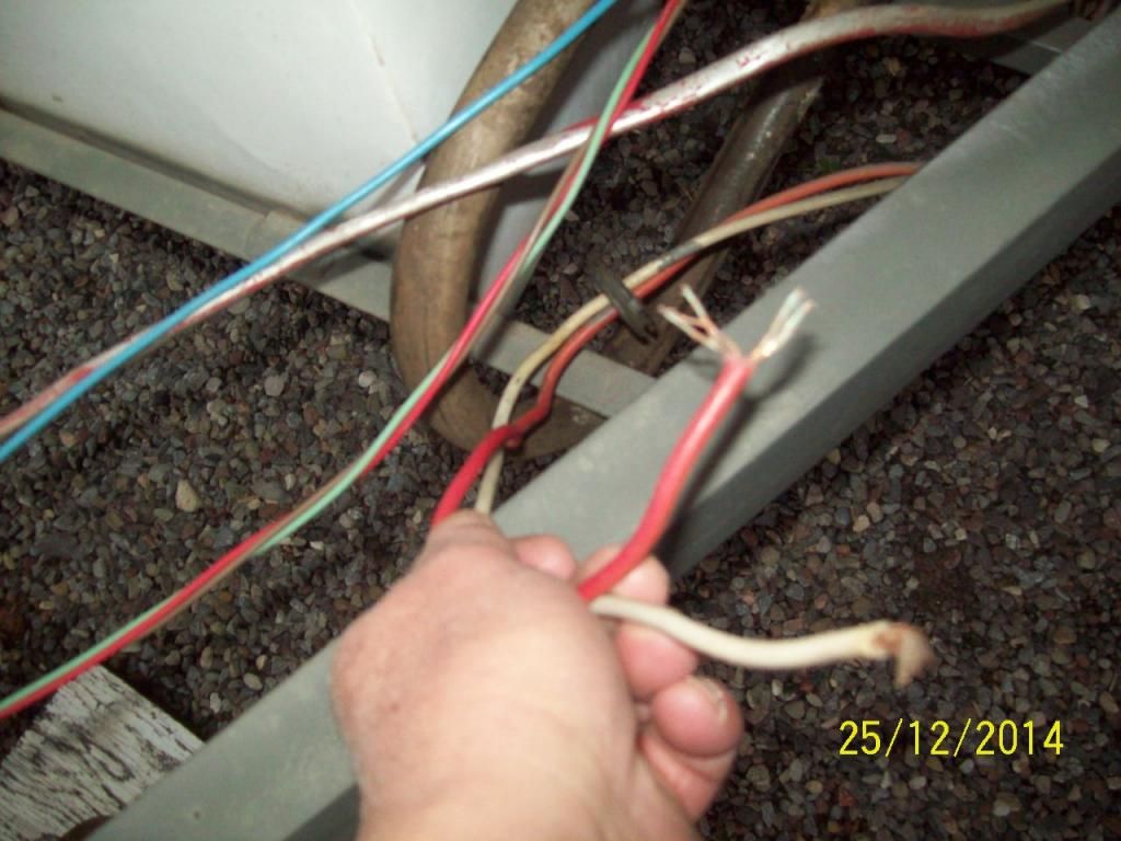 And from the vehicle plug: (Plan is for the junction block and new pigtail tying this together.) ![]() 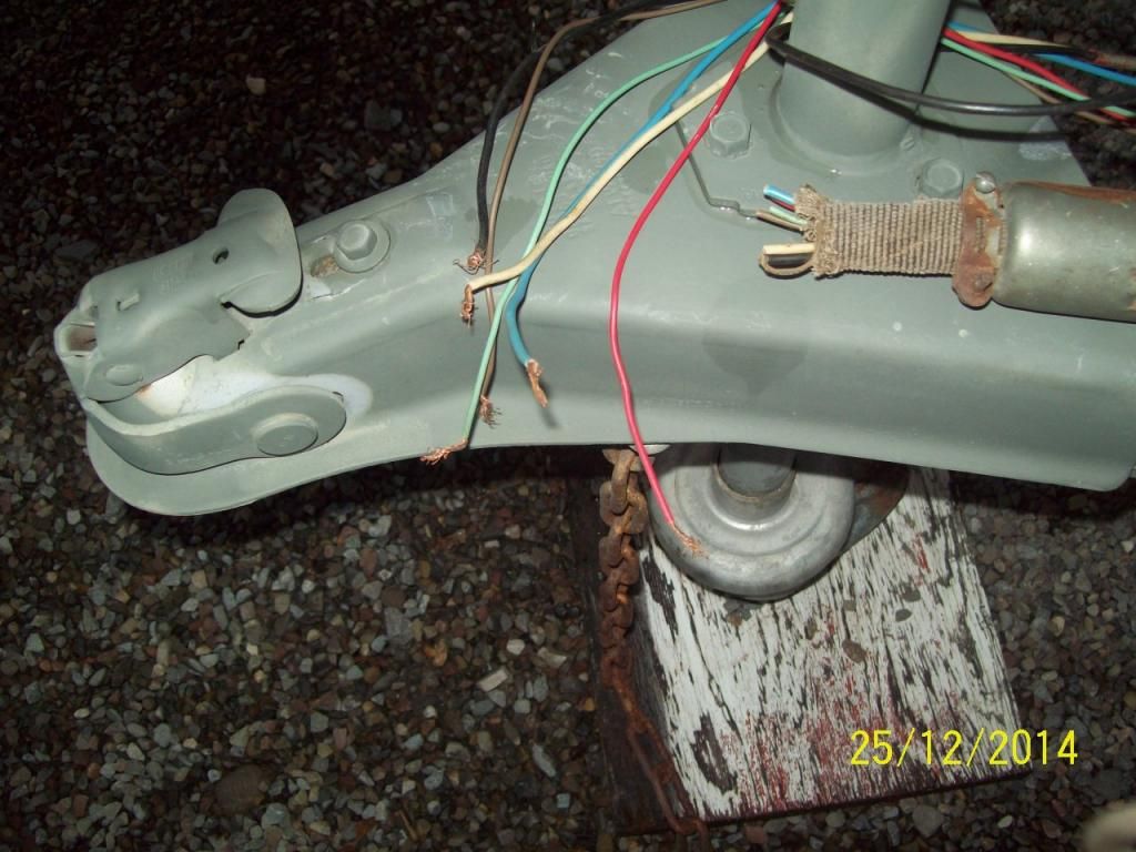 Fuse panel (Complete with the "Price Is Right" Hand Model...): 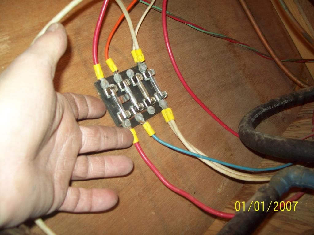 Green/brown/red "vehicle" lights run past the interior fuse block. Heavy red from the battery runs "through"; Blue feeds orange. The double "heavy" white is ground (is ground is ground)... The one is incoming from the battery post, other is out the same route and grounded to the frame, which grounds the entire system and the battery to any part of the trailer. 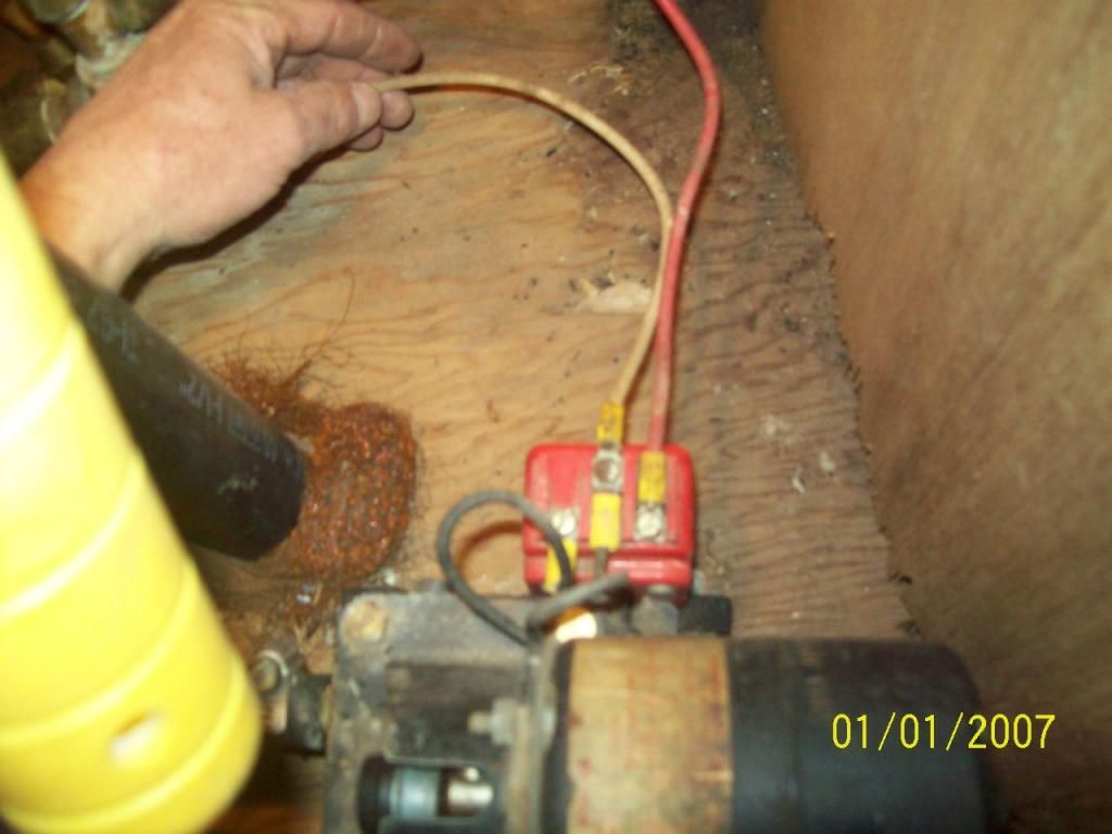 Termination point at the pump, this is the heavy red thru the fuse, by way of a switch; Heavy white (ground) thru the fuse panel. And now the only mystery left: 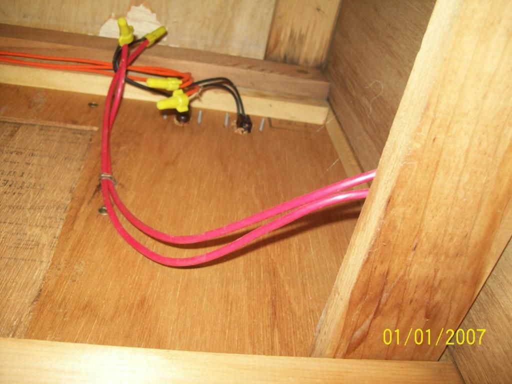 This view is looking up, beneath the refrigerator. The switch to the left is the one that works the pump. The one to the right is a mystery, and does not seem to run anything, although I think it may be the crossover between the vehicle feed and the battery, that allows the lights to work from the battery feed. Not proven yet though. Currently the 110 side of the camper is a single 15-amp breaker box. I am hoping to change it out to a 30-amp two-breaker box but that is a future project. (The converter box has not been installed in here yet, so I may build a "temporary feed" by plugging into an outlet with the test cord, or do the install later and upgrade the breaker box and inlet at the same time as installing the converter box.) All that for these two questions. First, Have I beat this too long and bored everyone to tears yet? and Second: Should the fuse panel in the trailer be eliminated when the converter is added, or tap into the existing lines? I think there should be no need for the fuses separate from the converter's panel. |
|
|
|
Post by vikx on Dec 25, 2014 21:41:12 GMT -8
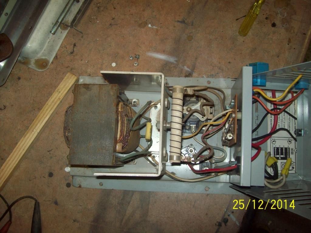
Great photos! I've seen that type of innards before. There's lots of testing you can do and some repairs, but I figure, if it works, use it, if not, replace.... I agree on the charging circuit, sounds OK. And it the transformer croaks, it's toast. This type of converter can generate heat; mounting with air gaps is a good idea.
I'm enjoying this thread! It is useful and will help others for sure.
The PO's wiring looks pretty good; neat and clean. The heavy red wires aren't necessary but certainly can carry most loads. Once reduced by the lighter black switch wires, not able to carry as many amps. Tracing where the orange wires end up may tell you what the 2nd switch is for. I'm certainly curious... Is there a 12 volt element for the fridge?
I think you're right on removing the first fuse block and using the converter block. Also, the Grounds would be better bolted to a bracket rather than fused. It's a fine connection, but since you're removing this block anyway, easy enough to do.
A note on the pump: it looks pretty hefty. I would check amp draw. There may be a reason for that heavy red wire.
Get back to us on your discoveries.
|
|
Ten
3K Member
Posts: 3,432
Likes: 1,467
70 Shasta 16SC + 1964 Airflyte
Currently Offline
|
Post by Ten on Dec 27, 2014 16:41:23 GMT -8
First out, thank you Vikx, for letting me pick your brain and for sharing your experience. You have confirmed my worst suspicions...that this is possible and I can go ahead and screw up what was original from the company. (I am pretty sure that all this is original and the PO's had nothing to do with changing the original.) I had hoped you would be interested enough to help, because I know you have some pretty extensive experience in this area. Since this gets to be fairly specific to the trailer, I suspect this line of questioning may be boring to the majority of folks joining us here, so I will try to keep it general in nature and as humorous as I can make it. The first step today was removing the fridge, and about 4300 cluster flies that were hibernating in the cabinet space. Then I tried fitting the converter in the space that I would have liked, which was below the sink. This spot on the floor is right where the 12-volt wiring enters the cabin, and is a bit of a "dead" space as far as any kind of storage goes. 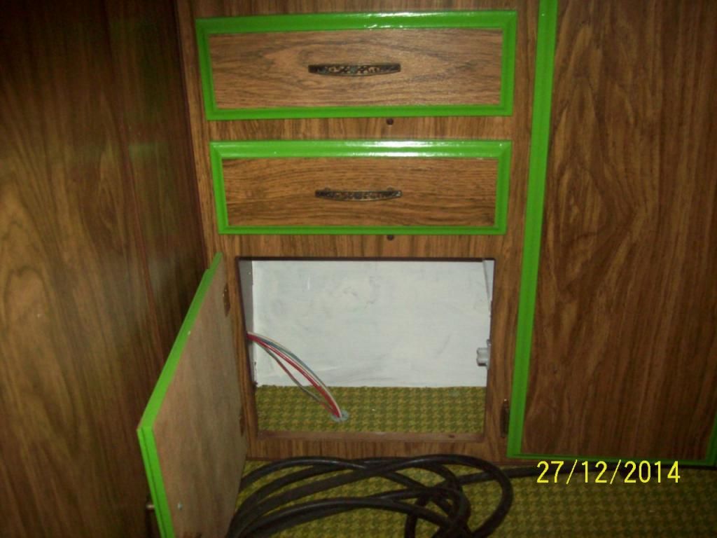 It did no t fit onto the floor as the cabinet of the converter is too wide to sit down, and mounting it up to the front wall was not possible as it would not allow access into the fuse panel. After a little more trial-and-error, I settled on here:  This is still in the same area, beneath that counter and also a dead storage space. It is however, open enough to allow the converter proper "breathing space". I can always drill a couple vent holes behind the stove to allow heat to escape by way of the vent if necessary, and there is room for a couple large pots beneath here. The wiring can be strapped to the front wall beneath the shelf and not be at risk of accidental damage. The heavy cord you see here is the one that I hooked up to bench test with and will be replaced. I tore some things apart again and ran a 12-2 indoor/outdoor-rated length of 110-V wire, between the closet and the utility hatch (where all this 12-v comes in). I am going to route it from the box to the converter and tie it all up out of the way. This will give me the option of a dedicated circuit for the converter....I think. On to the 110: This is what I have for a box...a single breaker (15A) and one circuit out. I added the outlet to the left of it last week, for the TV/DVD/antenna booster to plug in. (There are only a couple outlets, three lights, and the refrigerator that currently run on the 110....) 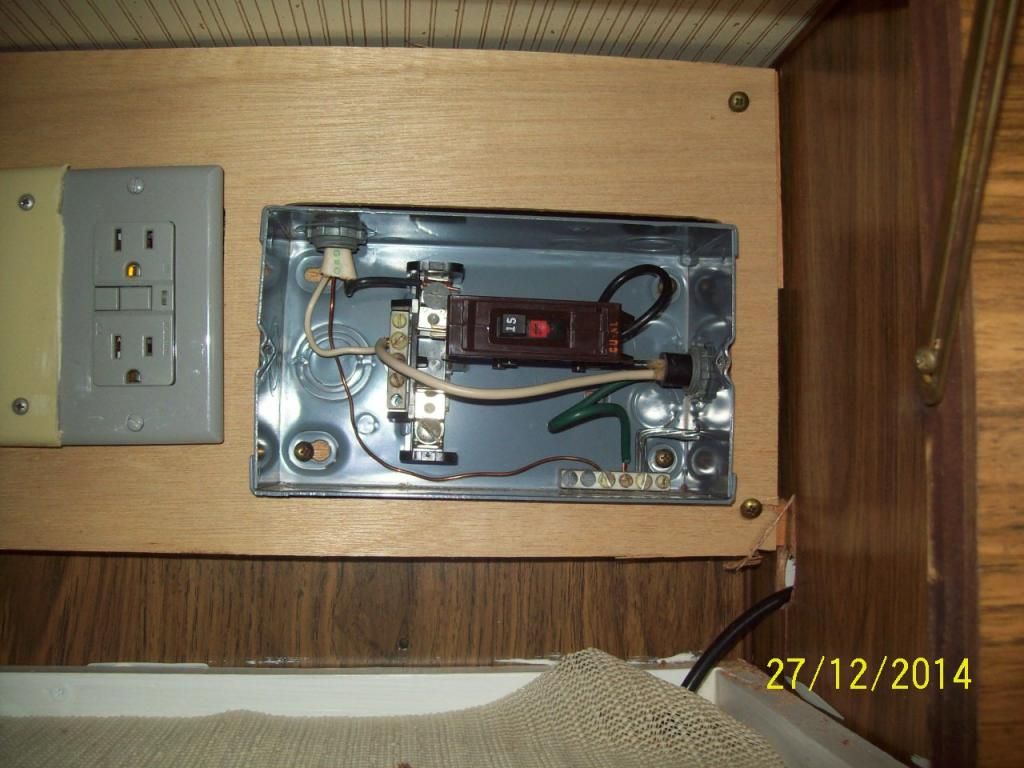 Cover: 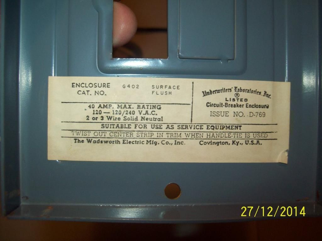 The way I am reading this, I should not have to change the box to upgrade to a 30-amp service, just add a breaker. That is if this type of breaker is still even available. (I purchased a 25-foot, 30-amp cord to change the inlet service already.) Question 1: Will I be able to find this type of breaker to add on with? (Footnote: I am really thinking out loud and have not even so much as tried to look for it as of this posting...research to follow...) Second question: Does the converter actually need to be on its own dedicated circuit? Or will it function alright if it's tied in with other functions? Question three: Is there any real advantage to the plug-in cord vs. the hardwired cord, which pulls out to plug into park service? I priced the Furrion Kit last week and the adaptors and socket parts run another $100. Okay. So now for the 12-volt side.... |
|
Ten
3K Member
Posts: 3,432
Likes: 1,467
70 Shasta 16SC + 1964 Airflyte
Currently Offline
|
Post by Ten on Dec 27, 2014 18:10:03 GMT -8
The refrigerator fits into the top cabinet, with the water heater directly below, and a void space in the bottom where all the 12-volt wiring is tied in and the water pump is located. The whole mess is lots easier to access without the fridge, so I pulled it out today, and got a couple last photos of the wires. This is the back side of the switches: 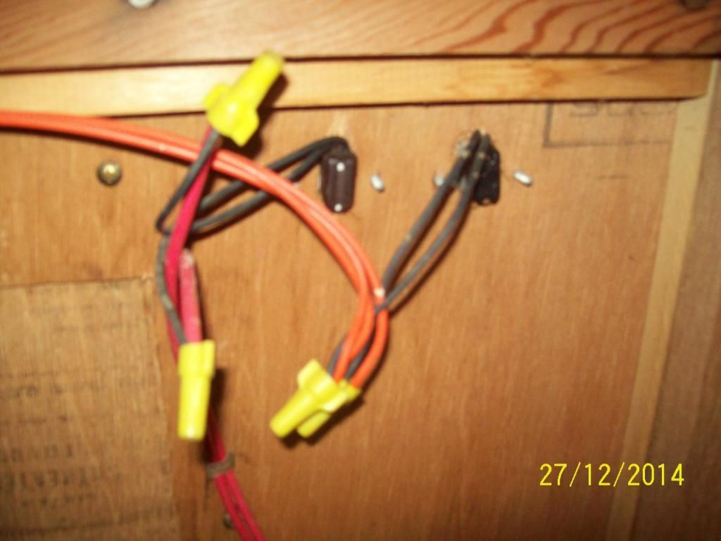 And the routing of the orange wires:  The orange wires are the feed for the 12-V lights. Note there is also a third (white) wire... a ground wire run for these lights, since they are mounted to the wood of the ceiling. The earlier mistake that I made was assuming that the lead to the switch was the single wire side, and then the "out" side of the switch carried the two wires. (Not real clear in the photo, but they are there....) It is the other way around...the two orange into the switch (hot side) come from the fuses and out to the cabin lights, bypassing the switch. The single wire comes out of the "ON" side of the switch, leading to the bathroom light....this switch needs to be on for the light to work, and it does. I assume (here we go again) that this feature was to keep from leaving the light on in the closed room without knowing it, and killing a battery. The lead to the pump is a 10-ga wire, which is rather heavy. I am not sure if that is an indication of a large draw, or a POTENTIAL large draw. Larger wire equals less resistance to draw equals lower amperage equals less heat (and other related problems). At least that is how I understand electricity to work. That and something about a kite and a key.... This still leaves me wondering why the system is divided, however, it does function with the lights working hooked to the vehicle, thus certain advantages for traveling and setup in the dark. Should the vehicle tie be eliminated with the addition of the converter? or is there any advantage to tying the vehicle to the trailer system? Or perhaps the potential to screw up the tow vehicle is too great? Boy I can hardly wait to get to the electric brakes! |
|
|
|
Post by vikx on Dec 27, 2014 21:12:20 GMT -8
OK, 110 here we go: NICE install on the converter! The breaker box is capable of 40 amps and will run a 2nd circuit with a new breaker. BUTT: Wadsworth breakers run about 45 bucks compared to $6 for a Square D... It might be worth it to change the breaker box out. I did some quick research and didn't see a common breaker that would replace the Wadsworth. They will work, but if one croaks in the middle of nowhere, not available... Do some more research and if a 2nd hand shop has a few extras, you're good to go. You have the option of one 15 amp circuit (original to the trailer) and a new circuit, 20 amps if you want. (of course 12/2 wiring on that) Consider the Square D QO Box: /QO24L69NRNM 60 amp 4 circuit load center www.homedepot.com/p/Square-D-QO-60-Amp-2-Space-4-Circuit-Outdoor-Main-Lug-Load-Center-with-Non-Metallic-Enclosure-and-Neutral-QO24L60NRNM/100174454The Converter should be OK on one 15 amp circuit. The trick is to keep the load down on that circuit. So, if you're going to run outlets for kitchen appliances, keep the converter on the other circuit. One of the few times I ran into a problem was with a newer trailer. The converter could pull 8 amps. The electric fireplace was on the same circuit, requiring 13 amps on high. Every time the owner used the heater, the breaker tripped. Oops. 13 + 8 = 21... You don't have to do a bunch of complicated additions, just use common sense. Also, with the newer box, you could dedicate one 15 amp circuit to the converter and perhaps the outside plug. Twin or Tandem breakers allow for 4 circuits. 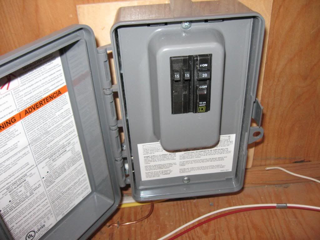 Usually, 3 circuits are plenty/overkill in a vintage trailer. Nice to have if a person wants to dedicate. Also, I think air conditioners should be run independent of the trailer wiring. In other words, drop the cord down thru the floor and use a 2nd receptacle at the campground. I have the Marinco (like Furrion) inlet and adapter on my Hanson. They are big and bulky. I think your 10ga 30 amp cord would be lighter weight and easier to handle. It depends on whether you want to stow the cord or be able to unplug. My trailers almost always have a 15 amp inlet. The wiring to the breaker box is always 10/2, so that an easy 30 amp upgrade is possible. It's rare that a smaller trailer would need much more than 15 amps. Again, depends on what the owner has in mind. |
|
|
|
Post by vikx on Dec 27, 2014 21:53:03 GMT -8
And 12 Volt: Your assumptions seem correct to me. The first fuse (actually a terminal) block is interesting and kind of a conversation piece. I would remove it because it's just another weak "link" to troubleshoot but the look is Cool. The heavy wiring will work, just fuse for the lightest wire on that circuit. (skinny wires on the switches) The pump may be labeled for amp draw... Here's my thoughts on the vehicle line: Wire the 7 way receptacle as listed, correct universal color code. You KNOW I will yell if there's any deviation. LOL. Your tow wiring is red, green and brown. Ground is white. Blue is Brake hot. Now here's where *I think* the difference comes in: The trailer as it is now is using Green (TM) to power the 12 volt lights from the vehicle? Test to be sure. 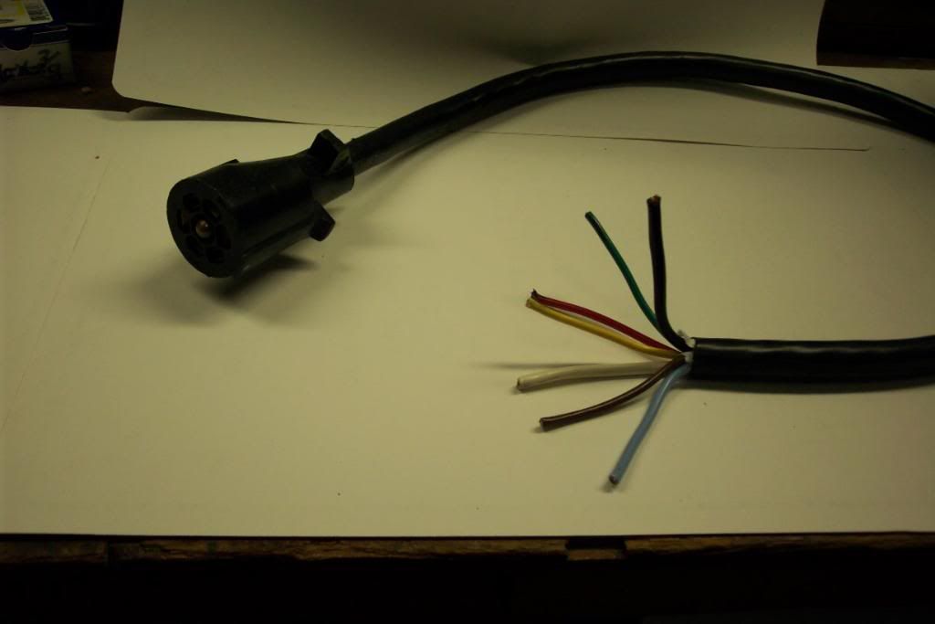 7 way black is 12 volt Hot. That wire is a charge line for the trailer battery while on the road. It will also power the trailer 12 volt system. I run the 7 way cord into the tongue area J box. There, Black is connected to battery hot. Use of a self resetting circuit breaker is recommended, both wires go on the Batt labeled stud. Trailer hot (minimum 12ga) into the trailer goes on the AUX stud. 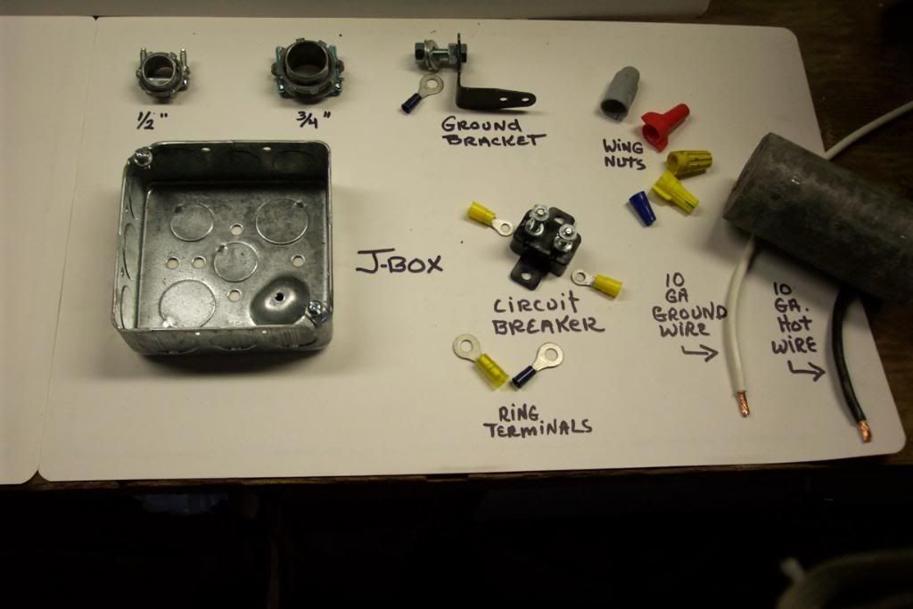  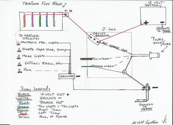 The Trailer Hot goes to your converter Hot lug. I'm assuming this would be the heavy duty lug on circuit #4. Converter schematic should tell you what goes where. Let us know! The converter should not interfere with your tow vehicle. (modern autos have safety diodes, etc, etc) Also, many turn the Hot off with the ignition. Another thing to research.. Normally, you would disconnect the 7 way before plugging the trailer in, so no interaction there. BRAKES are easy/peasy. Lets start another thread for them. |
|
Ten
3K Member
Posts: 3,432
Likes: 1,467
70 Shasta 16SC + 1964 Airflyte
Currently Offline
|
Post by Ten on Dec 28, 2014 18:03:20 GMT -8
I worked on it a little bit today. I have the converter hooked into the system, with just the single breaker for now. I tried looking up the Square D box, but it is listed as out of stock, and I am not so sure it isn't discontinued. But I did just start to look. I went to the store and got the wire I need to hook up the 12-volt. 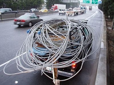 And I think I have enough to finish the 110 side: 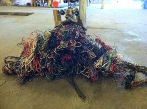 |
|
|
|
Post by vikx on Dec 28, 2014 22:26:42 GMT -8
ACK!!!
As long as you have the one circuit up and running, it's easy to design the next and have Light to do it by.
My Home Depot has one of the load centers in stock. Sometimes you can find the smaller metal ones at a 2nd hand shop...
|
|
Ten
3K Member
Posts: 3,432
Likes: 1,467
70 Shasta 16SC + 1964 Airflyte
Currently Offline
|
Post by Ten on Apr 5, 2015 16:05:49 GMT -8
It has been a while since the northeast got sunk into the deep freeze and the work outdoors screeched to a halt. The last few days have been better, and I got a couple days during the week when it got up to 61 to go work on the wiring. The 12-volt is all tied in together now with the converter, and the maintainer circuit appears to be working perfectly. I could not be more thrilled. Here is the wiring end of the converter: ![]() 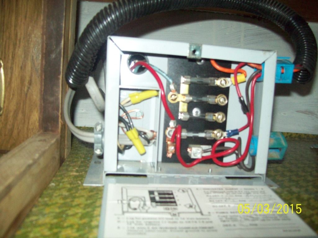 Wiring crossed underneath the cabinet and out to the fuse block: 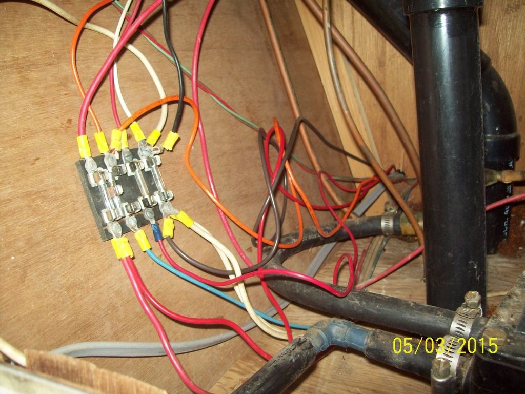 I tapped in through the existing block rather than cutting it out, although I am leaning toward cutting it out when it warms back up again. The power lead into the battery and pump are hooked to the battery side, so it crosses the fuse to hit the pump side. The orange wire feeds the overhead light circuit, but I hit on the light-side, and took the fuse out of the block. This was the circuit that lead in from the tow vehicle plug. This puts the lights on the battery instead of the vehicle. I left it so I can hook back to the vehicle if I want later. I added a lead that comes off the "clean" lug, and as of now only feeds a cigar plug, added where the switches are in the kitchen. I'm going to add another cigar plug. The ground side is a little ridiculous now, with additional 3 wires into the block. There is not any need for the fuse, so it will probably tie together and cut the fuse out also. 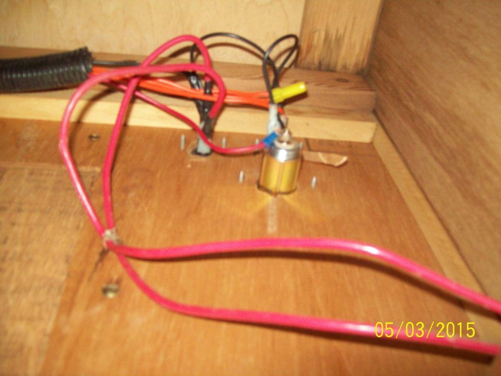 Switches are replaced, with the type that connects directly with blade connectors, rather than the thinner wires. These switches are rated for 30 amps, so there should not be any loss there. 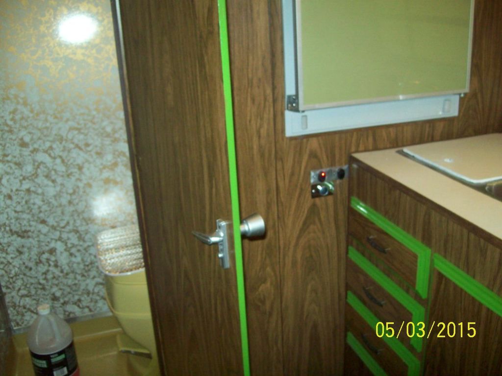 New power cord:  Battery in the system. That gauge stays right in the middle of the green: 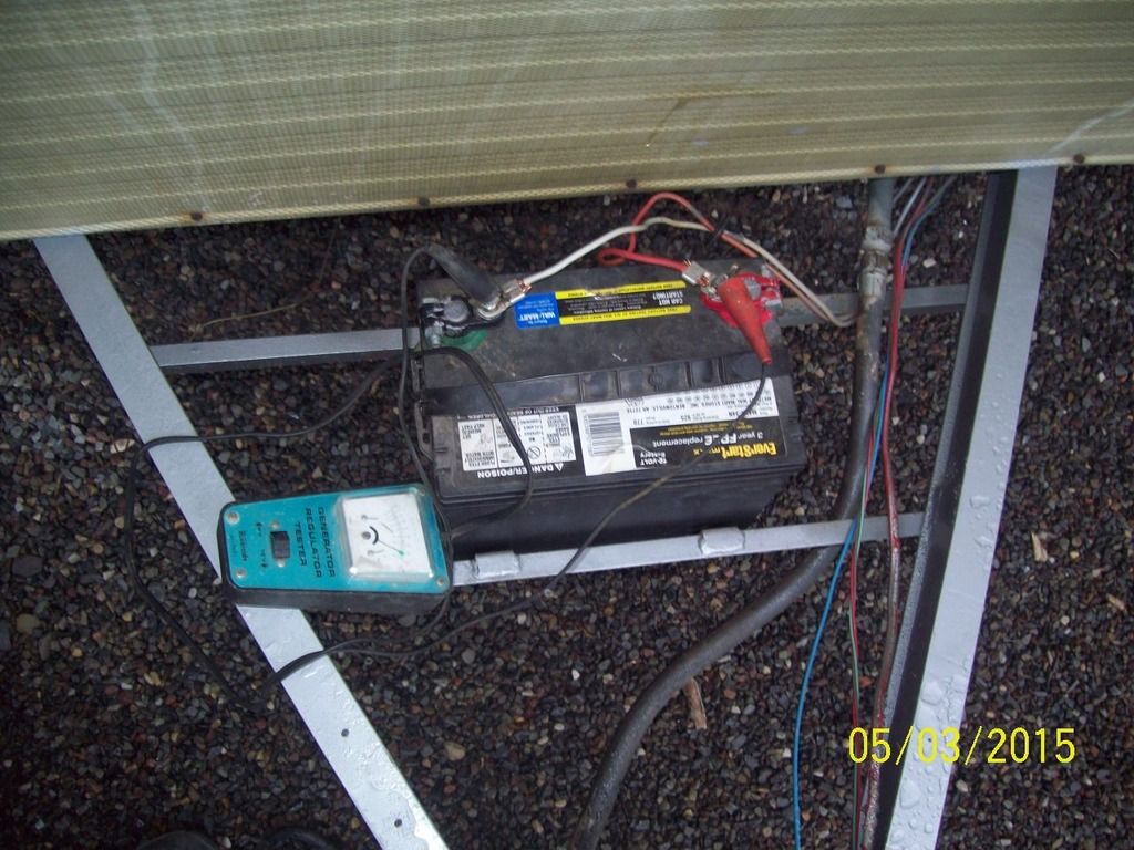 Cool as can be, 12-volt lights when plugged in. 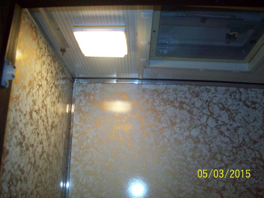 |
|
|
|
Post by vikx on Apr 5, 2015 22:23:39 GMT -8
Thanks so much for the update! I hope all of our members read this and learn. It's a great thread.
|
|
Ten
3K Member
Posts: 3,432
Likes: 1,467
70 Shasta 16SC + 1964 Airflyte
Currently Offline
|
Post by Ten on Aug 10, 2015 18:30:04 GMT -8
I hate to dredge this subject all back up again, but have a question...
I have been using a car battery in the SC to anchor this 12-V system, one that I use in my haul trailer. The hauler has a winch and electric jack on it so it does not leave the yard without the battery. I used it over the last weekend and have the battery still in the haul trailer.
It has tested well this summer, with a voltmeter attached the whole time it has been in operation, the meter reads a constant ~14 volts with the AC plugged in. Does not matter if it is plugged for a few hours or a few weeks, the voltage stays about the same. During any times the battery has been removed, I have kept it unplugged from the AC.
My question is this...
Is it okay to plug in the trailer and the converter, without the buffer of the battery in the system? Or am I running the risk of burning the maintainer out of the converter system?
|
|
|
|
Post by vikx on Aug 10, 2015 21:18:30 GMT -8
I've heard both ways: use it without the battery, you MUST have a battery...
Thing is, odd things can happen without the battery. I had lights that were bright, then others that weren't. Just strange. I'd use a battery, not sure about causing damage to the converter.
Note: this may not be related, but the self resetting circuit breaker "died" when I was using the system sans battery.
|
|